Problem 3.1 Consider a ray transfer matrix
between two planes.
(a) Suppose that any ray that is parallel to the optical axis in the first plane goes through a point on the optical axis in the second plane. This means that the second plane is the focal plane of the system. What does this imply for the elements of the transfer matrix?
(b) Suppose that the first plane is a focal plane so that any ray emitted by the point on the optical axis in this plane becomes collimated in the second plane. What does this imply for the elements for the transfer matrix?
(c) Consider two thin lenses with distance and focal distances and . Derive the transfer matrix linking the plane immediately before the first lens with the plane immediately behind the second lens. You may assume that the lenses are in air with refractive index .
(d) Use the condition that you found in a) to derive the back focal distance of a system consisting of two thin lenses with refractive index and and distance . Verify that the result agrees with the distance for the back focal plane in Section 4. Hint: let be the distance of the back focal point of the two-lens system to the second lens. Write the transfer matrix between the lens immediately before the first lens and the plane through the back focal point.
(e) Add a third thin lens with refractive index in contact to the second lens. Answer question c) for this system.
Problem 3.2 The eye and the magnifying glass.
In this problem the eye is modeled as a single thin lens that creates an image on the retina.
The distance between the retina and the lens is . Let us call the focal length of the lens . The eye is capable of varying .
(a) Suppose that the relaxed eye can see far-away objects sharply. How are and related for a relaxed eye?
(b) Suppose we want to see an object that is nearby, with coordinate , say. What should be to obtain a sharp image on the retina?
(c) We introduce a magnifying glass, i.e. we put a thin lens with focal length in front of the eye. In front of the magnifying glass, there is a nearby object. We want to place the object such that a completely relaxed eye can see it sharply. Where should the object be? Verify your answer using the applet found here:
https://
(d) Calculate the magnification of the system by using the transfer matrices. Assume for simplicity that throughout the entire system . How does the magnification of the object depend on ? Verify your answer with the applet.
Problem 3.3 Increasing the angular field of view.
Patients with tunnel vision have only a limited field of view because only the central region of their retina is light sensitive. Suppose that the sensitive region of the retina is circular and has radius . The length of the eye is 24 \text{cm} and the cornea and crystalline lens are together treated as a single thin lens.
(a) Show that the angular field of view of distant objects is
(take into account that the ray which enters the center of the eye lens is refracted because the vitreous humor has refractive index ).
(b) Use a negative lens with focal distance at a distance in front of the eye. Show that when
the angular field of view is increased by a factor 10.
(c) We require that the virtual images of all distant objects are at distance of at least the distance of the normal near point. This implies that we require that . Derive and the strength of the negative lens in diopter.
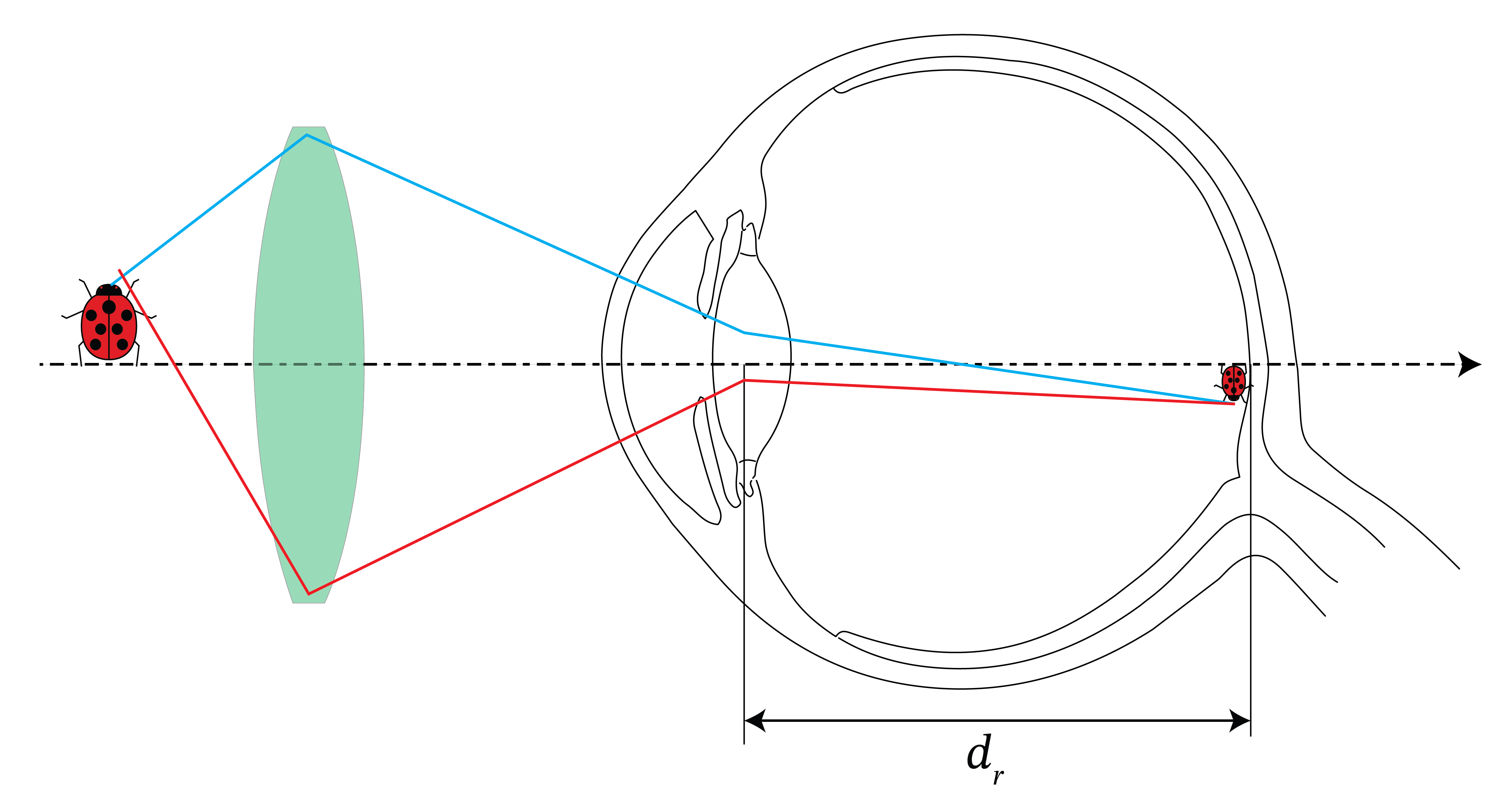
Figure 7:Angular view without and with the use of a negative lens.
Problem 3.4 * Imaging with a planar interface. In this problem we investigate whether it is possible to image an object with a single planar interface.
(a) We have two media with refractive indices and , separated by a planar interface. Give the transfer matrix for refraction at a planar interface using the paraxial approximation.
(b) Suppose we have an object that is a distance from the interface. Give the system matrix that describes a ray propagating from the object to the plane that is a distance behind the interface (see Figure 2).
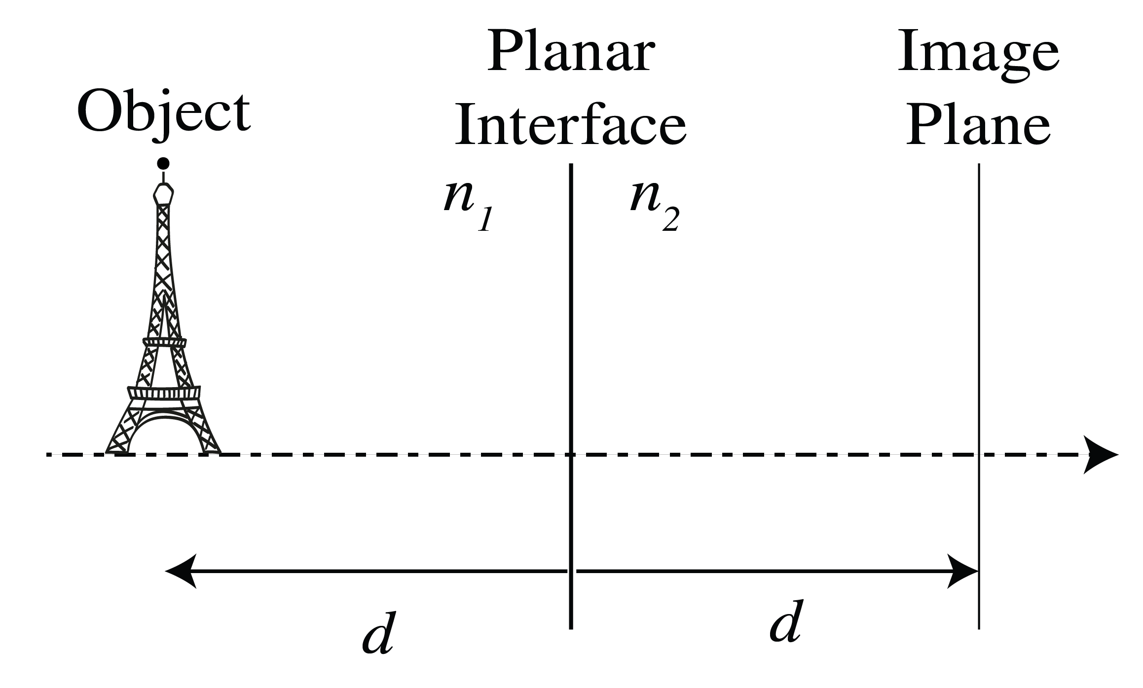
Figure 2:Planar interface between two media with different refractive indices. An object at distance d from the interface on the left side can potentially form an image at distance d on the right side, demonstrating the principle of a Veselago lens when the refractive index condition is satisfied.
(c) Assuming that , what condition has to be fulfilled in order to create an image in the plane behind the interface? Such an imaging system is called a Veselago lens.