. This force can easily be large enough to move the wire, since typical currents consist of very large numbers of moving charges.")
Because charges ordinarily cannot escape a conductor, the magnetic force on charges moving in a conductor is transmitted to the conductor itself.
We can derive an expression for the magnetic force on a current by taking a sum of the magnetic forces on individual charges. (The forces add because they are in the same direction.) The force on an individual charge moving at the drift velocity ${v}_{d}$ is given by $F=qv_{d}B \sin \theta$ . Taking $B$ to be uniform over a length of wire $l$ and zero elsewhere, the total magnetic force on the wire is then $F=\left( qv_{d}B \sin \theta \right)\left(N\right)$ , where $N$ ** is the number of charge carriers in the section of wire of length $l$ . Now, $N= nV$ , where $n$ is the number of charge carriers per unit volume and $V$ is the volume of wire in the field. Noting that $V= Al$ , where $A$ is the cross-sectional area of the wire, then the force on the wire is $F=\left(qv_{d}B \sin \theta \right)\left( nAl\right)$ . Gathering terms,
Because $nqAv_{d}=I$ (see Current),
is the equation for _magnetic force on a length $l$ of wire carrying a current $I$ in a uniform magnetic field $B$ _, as shown in [Figure 2]. If we divide both sides of this expression by $l$ , we find that the magnetic force per unit length of wire in a uniform field is $\frac{F}{l}=IB \sin \theta$ . The direction of this force is given by RHR-1, with the thumb in the direction of the current $I$ . Then, with the fingers in the direction of $B$ , a perpendicular to the palm points in the direction of $F$ , as in [Figure 2].
 . Its direction is given by RHR-1.")
Calculate the force on the wire shown in [Figure 1], given $B=1.50 \text{T}$ , $l=5.00 \text{cm}$ , and $I= 20.0 \text{A}$. Strategy
The force can be found with the given information by using $F=IlB \sin \theta$ and noting that the angle $\theta$ between $I$ and $B$ is $90 \text{º}$, so that $\sin \theta =1$.
Solution
Entering the given values into $F=IlB \sin \theta$ yields
The units for tesla are $1 \text{T}=\frac{N}{\text{A}\cdot \text{m}}$ ; thus,
Discussion
This large magnetic field creates a significant force on a small length of wire.
Magnetic force on current-carrying conductors is used to convert electric energy to work. (Motors are a prime example—they employ loops of wire and are considered in the next section.) Magnetohydrodynamics (MHD) is the technical name given to a clever application where magnetic force pumps fluids without moving mechanical parts. (See [Figure 3].)

A strong magnetic field is applied across a tube and a current is passed through the fluid at right angles to the field, resulting in a force on the fluid parallel to the tube axis as shown. The absence of moving parts makes this attractive for moving a hot, chemically active substance, such as the liquid sodium employed in some nuclear reactors. Experimental artificial hearts are testing with this technique for pumping blood, perhaps circumventing the adverse effects of mechanical pumps. (Cell membranes, however, are affected by the large fields needed in MHD, delaying its practical application in humans.) MHD propulsion for nuclear submarines has been proposed, because it could be considerably quieter than conventional propeller drives. The deterrent value of nuclear submarines is based on their ability to hide and survive a first or second nuclear strike. As we slowly disassemble our nuclear weapons arsenals, the submarine branch will be the last to be decommissioned because of this ability (See [Figure 4].) Existing MHD drives are heavy and inefficient—much development work is needed.

where $I$ is the current, $l$ is the length of a straight conductor in a uniform magnetic field $B$, and $\theta$ is the angle between $I$ and $B$. The force follows RHR-1 with the thumb in the direction of $I$.
Draw a sketch of the situation in [Figure 1] showing the direction of electrons carrying the current, and use RHR-1 to verify the direction of the force on the wire.
Verify that the direction of the force in an MHD drive, such as that in [Figure 3], does not depend on the sign of the charges carrying the current across the fluid.
Why would a magnetohydrodynamic drive work better in ocean water than in fresh water? Also, why would superconducting magnets be desirable?
Which is more likely to interfere with compass readings, AC current in your refrigerator or DC current when you start your car? Explain.
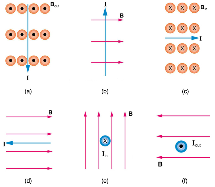
What is the direction of the magnetic force on the current in each of the six cases in [Figure 5]?
Strategy
The force on a current-carrying wire in a magnetic field follows the same right-hand rule as for moving charges. Point your thumb in the direction of conventional current $\vb{I}$, fingers in the direction of $\vb{B}$, and your palm pushes in the direction of the force $\vb{F}$. This is RHR-1 applied to current instead of velocity.
Solution
(a) Current $\vb{I}$ points down, $\vb{B}$ points out of page. Using RHR-1: thumb down, fingers out → palm pushes west (left).
(b) Current $\vb{I}$ points up, $\vb{B}$ points right. Using RHR-1: thumb up, fingers right → palm pushes into the page.
(c) Current $\vb{I}$ points right, $\vb{B}$ points into page. Using RHR-1: thumb right, fingers into page → palm pushes north (up).
(d) Current $\vb{I}$ points left, $\vb{B}$ points right. The current is antiparallel to the field, so $\theta = 180°$ and $\sin\theta = 0$. Therefore, there is no force.
(e) Current $\vb{I}$ points into page, $\vb{B}$ points up. Using RHR-1: thumb into page, fingers up → palm pushes east (right).
(f) Current $\vb{I}$ points out of page, $\vb{B}$ points left. Using RHR-1: thumb out of page, fingers left → palm pushes south (down).
Discussion
These are the same results as for positive charges moving in the same directions—this makes sense because conventional current is defined as the direction of positive charge flow. The case (d) shows why power transmission lines oriented parallel to Earth’s magnetic field experience no magnetic force.
(a) West (left); (b) Into page; (c) North (up); (d) No force; (e) East (right); (f) South (down).
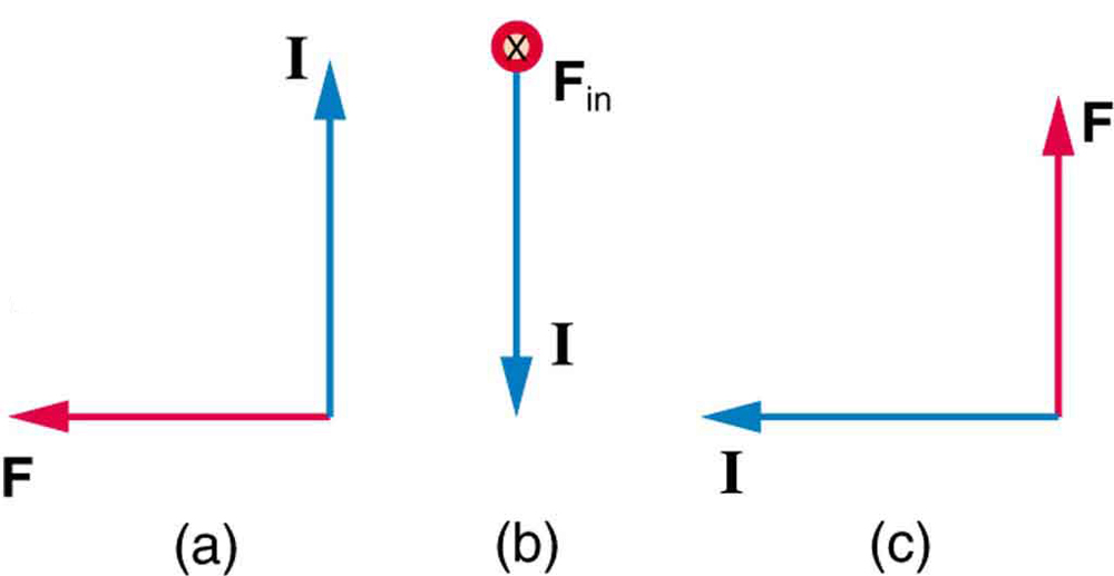
What is the direction of a current that experiences the magnetic force shown in each of the three cases in [Figure 6], assuming the current runs perpendicular to $B$ ?
Strategy
We work backwards using RHR-1. Given $\vb{F}$ and $\vb{B}$, we find $\vb{I}$. With fingers pointing along $\vb{B}$ and palm facing the direction of $\vb{F}$, the thumb points in the direction of current.
Solution
(a) Force $\vb{F}$ points up, $\vb{B}$ points out of page. Using RHR-1 in reverse: fingers out of page, palm facing up → thumb points east (right).
(b) Force $\vb{F}$ points up, $\vb{B}$ points right. Using RHR-1 in reverse: fingers right, palm facing up → thumb points out of the page.
(c) Force $\vb{F}$ points left, $\vb{B}$ points into page. Using RHR-1 in reverse: fingers into page, palm facing left → thumb points south (down).
Discussion
This inverse problem-solving technique is useful for designing electromagnetic devices. For instance, in an electric motor, you know the field direction and desired force direction, so you need to determine how to orient the current-carrying windings.
(a) East (right); (b) Out of the page; (c) South (down).
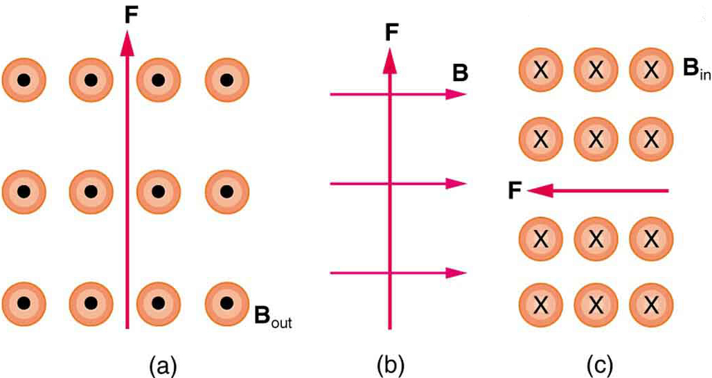
What is the direction of the magnetic field that produces the magnetic force shown on the currents in each of the three cases in [Figure 7], assuming $\vb{B}$ is perpendicular to $\vb{I}$ ?
Strategy
We work backwards using RHR-1. Given $\vb{F}$ and $\vb{I}$, we find $\vb{B}$ such that the cross product $\vb{I} \times \vb{B}$ gives the observed force direction.
Solution
(a) Current $\vb{I}$ points up, force $\vb{F}$ points left. Using RHR-1: thumb up ($\vb{I}$), palm facing left ($\vb{F}$) → fingers point into the page.
(b) Current $\vb{I}$ points down, force $\vb{F}$ points into page. Using RHR-1: thumb down, palm into page → fingers point west (left).
(c) Current $\vb{I}$ points left, force $\vb{F}$ points up. Using RHR-1: thumb left, palm up → fingers point out of the page.
Discussion
Finding the magnetic field direction from known force and current is important for magnetic field mapping. By measuring forces on calibrated current-carrying wires, we can determine both the magnitude and direction of unknown magnetic fields.
(a) Into the page; (b) West (left); (c) Out of the page.
(a) What is the force per meter on a lightning bolt at the equator that carries 20 000 A perpendicular to the Earth’s $3.00 \times 10^{-5} \text{-T}$ field? (b) What is the direction of the force if the current is straight up and the Earth’s field direction is due north, parallel to the ground?
Strategy
The force per unit length on a current-carrying wire is $F/L = BIL\sin\theta / L = BI\sin\theta$. For perpendicular orientation, $\sin\theta = 1$. For direction, we use RHR-1 with the current up and field north.
Solution
Known quantities:
(a) Force per meter:
(b) Direction:
Using RHR-1: current straight up (thumb up), field due north (fingers north) → palm pushes west.
Discussion
The force of 0.6 N/m seems modest for such an enormous current (20,000 A), but this is because Earth’s magnetic field is weak. Over a 1 km lightning bolt, this would be 600 N—significant but still small compared to the enormous electromagnetic forces within the lightning channel itself. The westward deflection is typically negligible compared to the irregular path lightning takes through the atmosphere.
(a) The force per meter is 0.600 N/m.
(b) The force direction is west (toward the left when facing north).
(a) A DC power line for a light-rail system carries 1000 A at an angle of $30.0 ^\circ$ to the Earth’s $5.00 \times 10^{-5} \text{-T}$ field. What is the force on a 100-m section of this line? (b) Discuss practical concerns this presents, if any.
Strategy
The force on a current-carrying conductor is $F = BIL\sin\theta$. Here we need to account for the angle between the current direction and the magnetic field. The wire length $L = 100$ m is the section in the field.
Solution
Known quantities:
(a) Force on the wire:
(b) Practical concerns:
This force of 2.50 N (about 0.56 pounds) on 100 m of wire is very small compared to:
Therefore, the magnetic force from Earth’s field is negligible and does not require special engineering consideration. Power line engineers worry far more about ice loading, wind, and thermal expansion than magnetic forces.
Discussion
If the wire were oriented perpendicular to the field ($\theta = 90°$), the force would double to 5.0 N, still negligible. The force would only become significant with much stronger fields (like near a large industrial electromagnet) or with very high currents.
(a) The force on the 100-m section is 2.50 N.
(b) This force is negligible compared to the wire’s weight and other structural loads. No special concerns arise from this magnetic force.
What force is exerted on the water in an MHD drive utilizing a 25.0-cm-diameter tube, if 100-A current is passed across the tube that is perpendicular to a 2.00-T magnetic field? (The relatively small size of this force indicates the need for very large currents and magnetic fields to make practical MHD drives.)
Strategy
In a magnetohydrodynamic (MHD) drive, current flows across a conducting fluid (like seawater) in a magnetic field, producing a force on the fluid that propels it. The force is $F = BIL$, where $L$ is the length of the current path—here, the tube diameter.
Solution
Known quantities:
Discussion
This 50 N force is only about 11 pounds—not nearly enough to effectively propel a marine vessel. For comparison, a small outboard motor produces thousands of newtons of thrust. The problem notes that this demonstrates why practical MHD drives require:
The Japanese experimental ship Yamato 1 (1992) used a 4 T superconducting magnet and achieved only about 8 knots. MHD drives are quiet (no propeller noise) but currently remain impractical for most applications due to their low efficiency and the engineering challenges of high-current, high-field systems in seawater.
The force on the water is 50.0 N, which is relatively small for propulsion purposes.
A wire carrying a 30.0-A current passes between the poles of a strong magnet that is perpendicular to its field and experiences a 2.16-N force on the 4.00 cm of wire in the field. What is the average field strength?
Strategy
We use $F = BIL\sin\theta$ and solve for the magnetic field $B$. Since the wire is perpendicular to the field, $\sin\theta = 1$.
Solution
Known quantities:
From $F = BIL$, solving for $B$:
Discussion
A field strength of 1.80 T is quite strong—achievable with high-quality permanent magnets (like neodymium-iron-boron) or with electromagnets. This type of measurement, using a known current and measuring the force on a known length of wire, is actually one way to measure magnetic field strength. The technique is called a current balance.
The average magnetic field strength is 1.80 T.
(a) A 0.750-m-long section of cable carrying current to a car starter motor makes an angle of $60 ^\circ$ with the Earth’s $5.50 \times 10^{-5} \text{T}$ field. What is the current when the wire experiences a force of $7.00 \times 10^{-3} \text{N}$ ? (b) If you run the wire between the poles of a strong horseshoe magnet, subjecting 5.00 cm of it to a 1.75-T field, what force is exerted on this segment of wire?
Strategy
Part (a) asks us to find current given force, field, length, and angle using $F = BIL\sin\theta$. Part (b) uses the current found in (a) with a different field and length to find force.
Solution
(a) Finding the current:
Known quantities:
From $F = BIL\sin\theta$, solving for $I$:
(b) Force in the horseshoe magnet:
Known quantities:
Discussion
The 196 A current is very high—typical of starter motor currents, which must deliver large power briefly. The force in Earth’s field is tiny (7 mN), but in the strong horseshoe magnet (1.75 T), the force on just 5 cm of wire is 17.2 N—enough to feel distinctly. This illustrates how the same current can experience vastly different forces depending on the magnetic environment.
(a) The current is 196 A.
(b) The force on the 5.00-cm segment in the 1.75-T field is 17.2 N.
(a) What is the angle between a wire carrying an 8.00-A current and the 1.20-T field it is in if 50.0 cm of the wire experiences a magnetic force of 2.40 N? (b) What is the force on the wire if it is rotated to make an angle of $90 ^\circ$ with the field?
Strategy
Part (a) uses $F = BIL\sin\theta$ solved for $\sin\theta$ to find the angle. Part (b) calculates the maximum force when perpendicular.
Solution
Known quantities:
(a) Finding the angle:
From $F = BIL\sin\theta$:
(b) Force at 90°:
Discussion
The force doubles when the wire is rotated from 30° to 90°. This is because $\sin(90°) = 1.00$ is twice $\sin(30°) = 0.50$. The angular dependence of magnetic force is important in motor design—maximum torque occurs when the coil plane is parallel to the field (so current is perpendicular to field).
(a) The angle between the wire and the magnetic field is $30°$.
(b) The force on the wire at 90° is 4.80 N.
The force on the rectangular loop of wire in the magnetic field in [Figure 8] can be used to measure field strength. The field is uniform, and the plane of the loop is perpendicular to the field. (a) What is the direction of the magnetic force on the loop? Justify the claim that the forces on the sides of the loop are equal and opposite, independent of how much of the loop is in the field and do not affect the net force on the loop. (b) If a current of 5.00 A is used, what is the force per tesla on the 20.0-cm-wide loop?

Strategy
We analyze the forces on each segment of the loop separately using RHR-1. The net force comes only from the bottom segment in the field. The force per tesla is $F/B = IL$.
Solution
(a) Direction and force analysis:
Looking at the figure:
Bottom segment: Current flows right, $\vb{B}$ is out of page. Using RHR-1: thumb right, fingers out → force is upward (into the field region).
Left side segment: Current flows down. Where this segment is in the field, $\vb{B}$ is out of page. Force is to the left.
Right side segment: Current flows up. Where this segment is in the field, $\vb{B}$ is out of page. Force is to the right.
The left and right side forces are equal and opposite because:
Therefore, these horizontal forces cancel regardless of how much of the loop is in the field. The only unbalanced force is from the bottom segment—the net force is upward (into the field region).
(b) Force per tesla:
For the bottom segment (width $L = 20.0$ cm = 0.200 m):
Discussion
This configuration is the basis of a current balance, used historically to define the ampere. By measuring the force and knowing the current and dimensions, the field strength can be determined. Alternatively, with a known field, the current can be measured. The key insight is that only the segment perpendicular to its own direction and in the field contributes to the net force.
(a) The net force on the loop is directed upward (into the field region). The forces on the left and right sides are equal and opposite because they carry equal currents in opposite directions through equal lengths of the same uniform field, so they cancel and do not contribute to the net force.
(b) The force per tesla on the loop is 1.00 N/T.