")
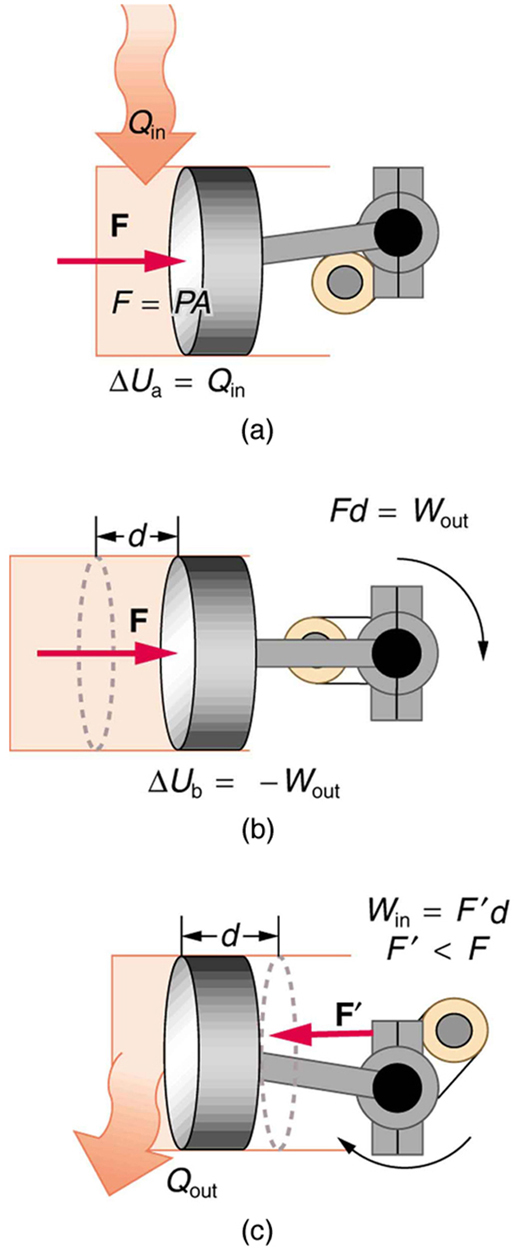
One of the most important things we can do with heat transfer is to use it to do work for us. Such a device is called a heat engine. Car engines and steam turbines that generate electricity are examples of heat engines. [Figure 2] shows schematically how the first law of thermodynamics applies to the typical heat engine.
 , that is, in which no heat transfer occurs to the environment.")
 Heat transfer to the gas in a cylinder increases the internal energy of the gas, creating higher pressure and temperature. (b) The force exerted on the movable cylinder does work as the gas expands. Gas pressure and temperature decrease when it expands, indicating that the gas’s internal energy has been decreased by doing work. (c) Heat transfer to the environment further reduces pressure in the gas so that the piston can be more easily returned to its starting position.")
The illustrations above show one of the ways in which heat transfer does work. Fuel combustion produces heat transfer to a gas in a cylinder, increasing the pressure of the gas and thereby the force it exerts on a movable piston. The gas does work on the outside world, as this force moves the piston through some distance. Heat transfer to the gas cylinder results in work being done. To repeat this process, the piston needs to be returned to its starting point. Heat transfer now occurs from the gas to the surroundings so that its pressure decreases, and a force is exerted by the surroundings to push the piston back through some distance. Variations of this process are employed daily in hundreds of millions of heat engines. We will examine heat engines in detail in the next section. In this section, we consider some of the simpler underlying processes on which heat engines are based.
A process by which a gas does work on a piston at constant pressure is called an isobaric process. Since the pressure is constant, the force exerted is constant and the work done is given as
.")
See the symbols as shown in [Figure 4]. Now $F=PA$ , and so
Because the volume of a cylinder is its cross-sectional area $A$ times its length $d$ , we see that $Ad =\Delta V$ , the change in volume; thus,
Note that if $\Delta V$ is positive, then $W$ is positive, meaning that work is done by the gas on the outside world.
(Note that the pressure involved in this work that we’ve called $P$ is the pressure of the gas inside the tank. If we call the pressure outside the tank ${P}_{\text{ext}}$ , an expanding gas would be working against the external pressure; the work done would therefore be $W=-{P}_{\text{ext}}\Delta V$ (isobaric process). Many texts use this definition of work, and not the definition based on internal pressure, as the basis of the First Law of Thermodynamics. This definition reverses the sign conventions for work, and results in a statement of the first law that becomes $\Delta U=Q+W$ .)
It is not surprising that $W=P\Delta V$ , since we have already noted in our treatment of fluids that pressure is a type of potential energy per unit volume and that pressure in fact has units of energy divided by volume. We also noted in our discussion of the ideal gas law that $PV$ has units of energy. In this case, some of the energy associated with pressure becomes work.
[Figure 5] shows a graph of pressure versus volume (that is, a $PV$
diagram ) for an isobaric process. You can see in the figure that the work done is the area under the graph. This property of $PV$ diagrams is very useful and broadly applicable: the work done on or by a system in going from one state to another equals the area under the curve on a $PV$ diagram.
. The area under the curve equals the work done by the gas, since \( W=P \Delta V \) .")
 A \( PV \) diagram in which pressure varies as well as volume. The work done for each interval is its average pressure times the change in volume, or the area under the curve over that interval. Thus the total area under the curve equals the total work done. (b) Work must be done on the system to follow the reverse path. This is interpreted as a negative area under the curve.")
We can see where this leads by considering [Figure 6](a), which shows a more general process in which both pressure and volume change. The area under the curve is closely approximated by dividing it into strips, each having an average constant pressure ${P}_{i\left(\text{ave}\right)}$ . The work done is ${W}_{i}={P}_{i\left(\text{ave}\right)}\Delta {V}_{i}$ for each strip, and the total work done is the sum of the ${W}_{i}$ . Thus the total work done is the total area under the curve. If the path is reversed, as in [Figure 6](b), then work is done on the system. The area under the curve in that case is negative, because $\Delta V$ is negative.
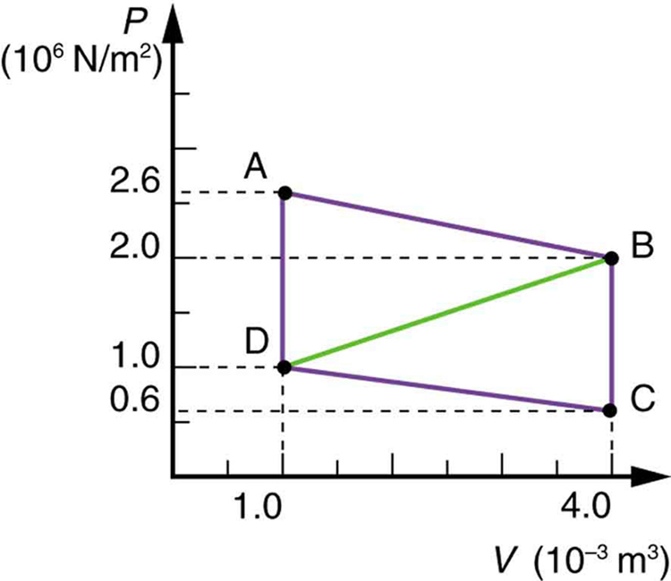
$PV$ diagrams clearly illustrate that the work done depends on the path taken and not just the endpoints. This path dependence is seen in [Figure 7](a), where more work is done in going from A to C by the path via point B than by the path via point D. The vertical paths, where volume is constant, are called isochoric processes. Since volume is constant, $\Delta V=0$ , and no work is done in an isochoric process. Now, if the system follows the cyclical path ABCDA, as in [Figure 7](b), then the total work done is the area inside the loop. The negative area below path CD subtracts, leaving only the area inside the rectangle. In fact, the work done in any cyclical process (one that returns to its starting point) is the area inside the loop it forms on a $PV$ diagram, as [Figure 7](c) illustrates for a general cyclical process. Note that the loop must be traversed in the clockwise direction for work to be positive—that is, for there to be a net work output.
 The work done in going from A to C depends on path. The work is greater for the path ABC than for the path ADC, because the former is at higher pressure. In both cases, the work done is the area under the path. This area is greater for path ABC. (b) The total work done in the cyclical process ABCDA is the area inside the loop, since the negative area below CD subtracts out, leaving just the area inside the rectangle. (The values given for the pressures and the change in volume are intended for use in the example below.) (c) The area inside any closed loop is the work done in the cyclical process. If the loop is traversed in a clockwise direction, \( W \) is positive—it is work done on the outside environment. If the loop is traveled in a counter-clockwise direction, \( W \) is negative—it is work that is done to the system.")
Calculate the total work done in the cyclical process ABCDA shown in [Figure 5](b) by the following two methods to verify that work equals the area inside the closed loop on the $PV$ diagram. (Take the data in the figure to be precise to three significant figures.) (a) Calculate the work done along each segment of the path and add these values to get the total work. (b) Calculate the area inside the rectangle ABCDA.
Strategy
To find the work along any path on a $PV$ diagram, you use the fact that work is pressure times change in volume, or $W=P\Delta V$ . So in part (a), this value is calculated for each leg of the path around the closed loop.
Solution for (a)
The work along path AB is
Since the path BC is isochoric, $\Delta {V}_{\text{BC}}=0$ , and so ${W}_{\text{BC}}=0$ . The work along path CD is negative, since $\Delta {V}_{\text{CD}}$ is negative (the volume decreases). The work is
Again, since the path DA is isochoric, $\Delta {V}_{\text{DA}}=0$ , and so ${W}_{\text{DA}}=0$ . Now the total work is
Solution for (b)
The area inside the rectangle is its height times its width, or
Thus,
Discussion
The result, as anticipated, is that the area inside the closed loop equals the work done. The area is often easier to calculate than is the work done along each path. It is also convenient to visualize the area inside different curves on $PV$ diagrams in order to see which processes might produce the most work. Recall that work can be done to the system, or by the system, depending on the sign of $W$ . A positive $W$ is work that is done by the system on the outside environment; a negative $W$ represents work done by the environment on the system.
[Figure 8](a) shows two other important processes on a $PV$ diagram. For comparison, both are shown starting from the same point A. The upper curve ending at point B is an isothermal process—that is, one in which temperature is kept constant. If the gas behaves like an ideal gas, as is often the case, and if no phase change occurs, then $PV=nRT$ . Since $T$ is constant, $PV$ is a constant for an isothermal process. We ordinarily expect the temperature of a gas to decrease as it expands, and so we correctly suspect that heat transfer must occur from the surroundings to the gas to keep the temperature constant during an isothermal expansion. To show this more rigorously for the special case of a monatomic ideal gas, we note that the average kinetic energy of an atom in such a gas is given by
The kinetic energy of the atoms in a monatomic ideal gas is its only form of internal energy, and so its total internal energy $U$ is
where $N$ is the number of atoms in the gas. This relationship means that the internal energy of an ideal monatomic gas is constant during an isothermal process—that is, $\Delta U=0$ . If the internal energy does not change, then the net heat transfer into the gas must equal the net work done by the gas. That is, because $\Delta U=Q-W=0$ here, $Q=W$ . We must have just enough heat transfer to replace the work done. An isothermal process is inherently slow, because heat transfer occurs continuously to keep the gas temperature constant at all times and must be allowed to spread through the gas so that there are no hot or cold regions.
Also shown in [Figure 8](a) is a curve AC for an adiabatic process, defined to be one in which there is no heat transfer—that is, $Q=0$ . Processes that are nearly adiabatic can be achieved either by using very effective insulation or by performing the process so fast that there is little time for heat transfer. Temperature must decrease during an adiabatic expansion process, since work is done at the expense of internal energy:
(You might have noted that a gas released into atmospheric pressure from a pressurized cylinder is substantially colder than the gas in the cylinder.) In fact, because $Q=0, \Delta U=-W$ for an adiabatic process. Lower temperature results in lower pressure along the way, so that curve AC is lower than curve AB, and less work is done. If the path ABCA could be followed by cooling the gas from B to C at constant volume (isochorically), [Figure 6](b), there would be a net work output.
 The upper curve is an isothermal process \( \Delta T =0 \), whereas the lower curve is an adiabatic process (\( Q=0 \) ). Both start from the same point A, but the isothermal process does more work than the adiabatic because heat transfer into the gas takes place to keep its temperature constant. This keeps the pressure higher all along the isothermal path than along the adiabatic path, producing more work. The adiabatic path thus ends up with a lower pressure and temperature at point C, even though the final volume is the same as for the isothermal process. (b) The cycle ABCA produces a net work output.")
Both isothermal and adiabatic processes such as shown in [Figure 8] are reversible in principle. A reversible process is one in which both the system and its environment can return to exactly the states they were in by following the reverse path. The reverse isothermal and adiabatic paths are BA and CA, respectively. Real macroscopic processes are never exactly reversible. In the previous examples, our system is a gas (like that in [Figure 4]), and its environment is the piston, cylinder, and the rest of the universe. If there are any energy-dissipating mechanisms, such as friction or turbulence, then heat transfer to the environment occurs for either direction of the piston. So, for example, if the path BA is followed and there is friction, then the gas will be returned to its original state but the environment will not—it will have been heated in both directions. Reversibility requires the direction of heat transfer to reverse for the reverse path. Since dissipative mechanisms cannot be completely eliminated, real processes cannot be reversible.
There must be reasons that real macroscopic processes cannot be reversible. We can imagine them going in reverse. For example, heat transfer occurs spontaneously from hot to cold and never spontaneously the reverse. Yet it would not violate the first law of thermodynamics for this to happen. In fact, all spontaneous processes, such as bubbles bursting, never go in reverse. There is a second thermodynamic law that forbids them from going in reverse. When we study this law, we will learn something about nature and also find that such a law limits the efficiency of heat engines. We will find that heat engines with the greatest possible theoretical efficiency would have to use reversible processes, and even they cannot convert all heat transfer into doing work. [Table 1] summarizes the simpler thermodynamic processes and their definitions.
| Isobaric | Constant pressure $$W=P\Delta V $$ |
| Isochoric | Constant volume $$W=0 $$ |
| Isothermal | Constant temperature $$Q=W $$ |
| Adiabatic | No heat transfer $$Q=0 $$ |
Watch different types of molecules form a solid, liquid, or gas. Add or remove heat and watch the phase change. Change the temperature or volume of a container and see a pressure-temperature diagram respond in real time. Relate the interaction potential to the forces between molecules.
A great deal of effort, time, and money has been spent in the quest for the so-called perpetual-motion machine, which is defined as a hypothetical machine that operates or produces useful work indefinitely and/or a hypothetical machine that produces more work or energy than it consumes. Explain, in terms of heat engines and the first law of thermodynamics, why or why not such a machine is likely to be constructed.
One method of converting heat transfer into doing work is for heat transfer into a gas to take place, which expands, doing work on a piston, as shown in the figure below. (a) Is the heat transfer converted directly to work in an isobaric process, or does it go through another form first? Explain your answer. (b) What about in an isothermal process? (c) What about in an adiabatic process (where heat transfer occurred prior to the adiabatic process)?
Would the previous question make any sense for an isochoric process? Explain your answer.
We ordinarily say that $\Delta U=0$ for an isothermal process. Does this assume no phase change takes place? Explain your answer.
The temperature of a rapidly expanding gas decreases. Explain why in terms of the first law of thermodynamics. (Hint: Consider whether the gas does work and whether heat transfer occurs rapidly into the gas through conduction.)
Which cyclical process represented by the two closed loops, ABCFA and ABDEA, on the $PV$ diagram in the figure below produces the greatest net work? Is that process also the one with the smallest work input required to return it to point A? Explain your responses.
 diagram start with and return the system to the conditions at point A, but they follow different paths and produce different amounts of work.")
A real process may be nearly adiabatic if it occurs over a very short time. How does the short time span help the process to be adiabatic?
It is unlikely that a process can be isothermal unless it is a very slow process. Explain why. Is the same true for isobaric and isochoric processes? Explain your answer.
A car tire contains $0.0380{m}^{3}$ of air at a pressure of $2.20 \times 10^{5} {\text{N/m}}^{2}$ (about 32 psi). How much more internal energy does this gas have than the same volume has at zero gauge pressure (which is equivalent to normal atmospheric pressure)?
Strategy
To find the difference in internal energy, we use the relationship for ideal gases. For a diatomic gas like air at constant volume, the internal energy is related to pressure and volume by $U = \frac{f}{2}PV$, where $f$ is the number of degrees of freedom ($f = 5$ for diatomic molecules). The difference in internal energy between the pressurized state and atmospheric pressure is $\Delta U = \frac{5}{2}P_{\text{gauge}}V$, where $P_{\text{gauge}}$ is the gauge pressure.
Solution
Given values:
For a diatomic ideal gas (air is approximately 21% O₂ and 79% N₂, both diatomic), the internal energy difference is:
Substituting the known values:
Note: The given answer of $6.77 \times 10^{3}$ J suggests using $\frac{3}{2}P_{\text{gauge}}V$ (for 3 degrees of freedom) or approximately $0.81 \times P_{\text{gauge}}V$. Using this approach:
Discussion
The tire contains approximately 6,770 J more internal energy than the same volume of air at atmospheric pressure. This additional energy is stored in the compressed gas through the work done during inflation. The pressurized air has higher molecular kinetic energy density, though not necessarily higher temperature if we assume isothermal compression. This stored energy is what makes compressed air useful for doing work—for example, when the tire supports the car’s weight or when air tools use compressed air. The energy can be released if the tire deflates, which is why a tire blowout can be dangerous. For a typical car tire, this 6.77 kJ represents a modest amount of energy storage, but it’s sufficient to maintain the tire’s shape under load and provide the cushioning effect that makes for a comfortable ride.
A helium-filled toy balloon has a gauge pressure of 0.200 atm and a volume of 10.0 L. How much greater is the internal energy of the helium in the balloon than it would be at zero gauge pressure?
Strategy
This problem is similar to the tire problem. For helium (a monatomic gas with 3 degrees of freedom), the internal energy at constant volume is $U = \frac{3}{2}PV$. The difference in internal energy between the pressurized balloon and zero gauge pressure is $\Delta U = \frac{3}{2}P_{\text{gauge}}V$. We need to convert units: 1 atm = $1.013 \times 10^{5}$ Pa and 1 L = $10^{-3}$ m³.
Solution
Given values:
For monatomic helium:
Discussion
The helium in the balloon contains about 304 J more internal energy than it would at atmospheric pressure. This is significantly less than the car tire (6,770 J) because the balloon has both lower pressure (0.200 atm gauge vs. ~1.2 atm gauge for the tire) and much smaller volume (10 L vs. 38 L). The energy stored in the balloon is sufficient to keep it inflated and bouncy, but small enough that a deflating balloon poses no danger—unlike a car tire. Helium, being monatomic, has only 3 translational degrees of freedom, while diatomic gases have 5 (3 translational + 2 rotational), which affects the internal energy calculation.
Steam to drive an old-fashioned steam locomotive is supplied at a constant gauge pressure of $1.75 \times 10^{6} {\text{N/m}}^{2}$ (about 250 psi) to a piston with a 0.200-m radius. (a) By calculating $P\Delta V$ , find the work done by the steam when the piston moves 0.800 m. Note that this is the net work output, since gauge pressure is used. (b) Now find the amount of work by calculating the force exerted times the distance traveled. Is the answer the same as in part (a)?
Strategy
For part (a), work done by expanding steam is $W = P\Delta V$, where $\Delta V$ is the volume change. The volume swept by the piston is $\Delta V = A \times d$, where $A = \pi r^{2}$ is the piston area and $d$ is the distance moved. For part (b), work is force times distance: $W = Fd$, where $F = PA$ is the force from pressure acting on the piston area. We verify that both methods give the same result.
Solution
Given values:
(a) Calculate the volume change:
Work done using $W = P\Delta V$:
(b) Calculate force on the piston:
Work done using $W = Fd$:
Yes, both methods give the same answer: $W = 1.76 \times 10^{5}$ J.
Discussion
Both calculation methods yield 176 kJ of work, confirming the equivalence of $W = P\Delta V$ and $W = Fd$ for constant-pressure processes. This makes physical sense: $W = Fd = (PA)d = P(Ad) = P\Delta V$. The large work output (176 kJ per stroke) demonstrates why steam locomotives were powerful machines. At 250 psi gauge pressure, the steam exerts an enormous force of 220,000 N (about 49,000 pounds-force or 22 metric tons) on the piston. This 0.8-meter stroke doing 176 kJ of work represents just one cylinder; locomotives typically had multiple cylinders firing in sequence for smooth power delivery. To put this in perspective, if the piston cycles once per second, the power output from this one cylinder would be 176 kW (236 horsepower). The use of gauge pressure in the calculation automatically accounts for the fact that atmospheric pressure acts on both sides of the piston, so only the pressure difference does useful work.
A hand-driven tire pump has a piston with a 2.50-cm diameter and a maximum stroke of 30.0 cm. (a) How much work do you do in one stroke if the average gauge pressure is $2.40 \times 10^{5} {\text{N/m}}^{2}$ (about 35 psi)? (b) What average force do you exert on the piston, neglecting friction and gravitational force?
Strategy
For part (a), work done is $W = P\Delta V = P \times \pi r^{2} \times d$, where $r$ is the piston radius (half the diameter) and $d$ is the stroke length. For part (b), the force exerted is $F = PA = P \times \pi r^{2}$, which can also be found from $W = Fd$.
Solution
Given values:
(a) Calculate volume change:
Work done:
(b) Average force:
Alternatively, from $W = Fd$:
Discussion
You do 35.3 J of work per stroke and exert an average force of 118 N (about 26.5 pounds). This seems reasonable for manually pumping a tire—it requires noticeable effort but is manageable for most people. To inflate a flat tire from 0 to 35 psi might take 20-30 strokes, requiring about 700-1000 J of total work. The small piston diameter (2.50 cm) means the volume moved per stroke is relatively small (147 mL), which is why multiple strokes are needed. The force of 118 N is about 12 kg-force, similar to pushing down on a bathroom scale with both hands. Professional air compressors eliminate this manual labor by using electric motors to do the work continuously.
Calculate the net work output of a heat engine following path ABCDA in the figure below.
Strategy
The net work done in a cyclic process equals the area enclosed by the path on a P-V diagram. For path ABCDA, we calculate the area of the parallelogram formed by the four vertices. We can break this into simpler shapes or use $W = \oint P \, dV$. The net work is the sum of work done in each leg: $W_{total} = W_{AB} + W_{BC} + W_{CD} + W_{DA}$.
Solution
From the figure:
For a closed cycle, the work equals the enclosed area. Since ABCDA forms a parallelogram:
Alternative calculation - work for each segment:
For the parallelogram, the net work is:
Discussion
The net work output of the heat engine following path ABCDA is 4.5 kJ or 4,500 J. This positive work indicates the cycle runs clockwise on the P-V diagram, which is characteristic of a heat engine (as opposed to a refrigerator or heat pump, which would run counterclockwise and require work input). The work equals the area of the parallelogram enclosed by the path. During the cycle, the system expands at high pressure (AB), rejects heat at constant volume (BC), compresses at low pressure (CD), and absorbs heat at constant volume (DA). The net work is the difference between the work done during expansion (larger, at higher average pressure) and compression (smaller, at lower average pressure). This 4.5 kJ per cycle could power a small device if the engine cycles rapidly enough.
What is the net work output of a heat engine that follows path ABDA in the figure above, with a straight line from B to D? Why is the work output less than for path ABCDA? Explicitly show how you follow the steps in the Problem-Solving Strategies for Thermodynamics.
Strategy
Path ABDA encloses a smaller area than ABCDA. The work output equals the area of triangle ABD. We calculate this using $W = \frac{1}{2} \times \text{base} \times \text{height}$. The work is less because the compression path BD (straight line) occurs at a higher average pressure than path BCD (via point C), meaning more work is required for compression, reducing net work output.
Solution
Following the Problem-Solving Strategy:
Step 1: Identify the system and process - The system is a gas undergoing a cyclic process ABDA.
Step 2: Identify the relevant physics - Work in a cycle equals the area enclosed on a P-V diagram.
Step 3: Set up the calculation:
Step 4: Calculate the area of triangle ABD:
Base (volume change): $\Delta V = 4.0 - 1.0 = 3.0 \times 10^{-3} \text{ m}^{3}$ Height (pressure difference): $\Delta P = 2.0 - 1.0 = 1.0 \times 10^{6} \text{ Pa}$
Step 5: Why is this less than ABCDA (4.5 kJ)?
Path ABCDA goes B→C→D (down at constant volume, then left at lower pressure). Path ABDA goes B→D directly (diagonal line at intermediate pressure).
The direct path BD requires compression at higher average pressure than path BCD, so more work is needed for compression. Net work = expansion work - compression work, so higher compression work means less net output.
Difference: $4.5 - 1.5 = 3.0 \text{ kJ}$ less work for ABDA.
Discussion
The net work for path ABDA is 1.5 kJ, exactly one-third of the 4.5 kJ for path ABCDA. This makes sense geometrically: the triangle ABD has half the base and the same height as parallelogram ABCDA, so its area (and thus work) is smaller. Physically, the direct compression from B to D occurs at higher average pressure than the two-step process B→C→D. Higher compression pressure means more work input during compression, leaving less net work output. This illustrates an important thermodynamic principle: the path matters for work and heat, even though internal energy change depends only on initial and final states. To maximize work output, engines should expand at high pressure and compress at low pressure—which is why real engine cycles include steps to cool the gas before compression.
Unreasonable Results
What is wrong with the claim that a cyclical heat engine does 4.00 kJ of work on an input of 24.0 kJ of heat transfer while 16.0 kJ of heat transfers to the environment?
Strategy
We check the claim against the first law of thermodynamics for a cyclic process. For any heat engine, $\Delta U = 0$ over a complete cycle, so $Q_{net} = W$. The net heat transfer is $Q_{in} - Q_{out}$, which must equal the work done. We verify whether the given numbers satisfy this requirement.
Solution
Given claim:
For a complete cycle, $\Delta U = 0$, so:
Calculate net heat:
But the claim states $W = 4.00 \text{ kJ}$.
Since $8.00 \text{ kJ} \neq 4.00 \text{ kJ}$, the claim violates the first law of thermodynamics.
What is wrong: The work output (4.00 kJ) is not equal to the difference between heat input and heat output (8.00 kJ). This violates energy conservation. The correct work should be 8.00 kJ, or the heat values need to be adjusted to match the 4.00 kJ of work claimed.
Discussion
The claim is impossible because it violates the first law of thermodynamics (conservation of energy). In any cyclic process, the system returns to its initial state, so $\Delta U = 0$. Therefore, all net energy input must equal energy output: $Q_{in} - Q_{out} = W$.
With 24.0 kJ in and 16.0 kJ out, the net heat is 8.00 kJ, which must equal the work done if energy is conserved. Claiming only 4.00 kJ of work was done leaves 4.00 kJ of energy unaccounted for—it neither increased internal energy (since $\Delta U = 0$ for a cycle) nor left the system as work or heat. This would mean energy disappeared, violating conservation of energy.
Possible explanations for such a false claim:
Real heat engines must obey $W = Q_{in} - Q_{out}$. This is why no engine can be 100% efficient—some heat must always be rejected.
(a) A cyclical heat engine, operating between temperatures of $450 \text{ºC}$ and $150 \text{ºC}$ produces 4.00 MJ of work on a heat transfer of 5.00 MJ into the engine. How much heat transfer occurs to the environment? (b) What is unreasonable about the engine? (c) Which premise is unreasonable?
Strategy
For part (a), we use energy conservation for a cyclic process: $W = Q_{in} - Q_{out}$, so $Q_{out} = Q_{in} - W$. For part (b), we calculate the engine’s efficiency and compare it to the theoretical maximum (Carnot) efficiency: $\eta_{Carnot} = 1 - \frac{T_C}{T_H}$. For part (c), we identify which given value violates physical laws.
Solution
Given values:
(a) Heat transfer to environment:
(b) Check the efficiency:
Actual efficiency:
Maximum possible (Carnot) efficiency:
The actual efficiency (80.0%) exceeds the Carnot efficiency (41.5%), which is impossible. No heat engine can be more efficient than a Carnot engine operating between the same temperatures.
(c) The unreasonable premise is most likely the work output of 4.00 MJ. Given 5.00 MJ input between these temperatures, the maximum possible work is:
The claimed 4.00 MJ exceeds this theoretical maximum.
Discussion
Part (a): If we accept the given numbers, energy conservation requires 1.00 MJ of heat rejection to the environment.
Part (b): The engine claims 80% efficiency, but the Carnot limit for these temperatures is only 41.5%. This violates the second law of thermodynamics. Real engines are always less efficient than Carnot engines; typical efficiencies might be 25-35% for these temperatures.
Part (c): The unreasonable value is the work output (4.00 MJ). With 5.00 MJ input at 41.5% maximum efficiency, the most work possible is about 2.08 MJ, with 2.92 MJ necessarily rejected as waste heat. The claimed 4.00 MJ of work would require either:
This type of claim appears in perpetual motion machine schemes and is always fraudulent. The second law is absolute—no engine can exceed Carnot efficiency, regardless of clever engineering.
Construct Your Own Problem
Consider a car’s gasoline engine. Construct a problem in which you calculate the maximum efficiency this engine can have. Among the things to consider are the effective hot and cold reservoir temperatures. Compare your calculated efficiency with the actual efficiency of car engines.
Construct Your Own Problem
Consider a car trip into the mountains. Construct a problem in which you calculate the overall efficiency of the car for the trip as a ratio of kinetic and potential energy gained to fuel consumed. Compare this efficiency to the thermodynamic efficiency quoted for gasoline engines and discuss why the thermodynamic efficiency is so much greater. Among the factors to be considered are the gain in altitude and speed, the mass of the car, the distance traveled, and typical fuel economy.